Tesla’s Worldwide electricity System.
The energy of the universe is manifesting in physical form and we have misinterpreted this manifestation by calling it God….just ideas made up by humans to explain something they don’t understand

“My first observations positively terrified me as there was present in them something mysterious, not to say supernatural, and I was alone in my laboratory at night”
– Nikola Tesla, 1901 article “Talking With The Planets“

Tesla’s Spirit Radio uses a simple crystal radio circuit connected to a computer sound-in jack to generate spooky sounds from all kinds of electromagnetic sources. As you will see, it creeped the hell out of Tesla himself.
“My first observations positively terrified me as there was present in them something mysterious, not to say supernatural, and I was alone in my laboratory at night.”
– Nikola Tesla 1901“The sounds I am listening to every night at first appear to be human voices conversing back and forth in a language I cannot understand. I find it difficult to imagine that I am actually hearing real voices from people not of this planet. There must be a more simple explanation that has so far eluded me.”
– Nikola Tesla 1918
Is it science or the supernatural? Check out the video to see what the radio is capable of and, if your are so inclined, build one and decide for yourself. Needless to say, this would be a hit at a Halloween party. Hit the link for a complete set of instructions.

News Flash!!!
The Spooky Tesla Spirit Radio and Mrfixitrick are now featured in a PC game called “Tesla”. Monsters and bats are battled, while helping Mrfixitrick find the seven parts of the Spooky Tesla Spirit Radio. Intriguing background music. From GODD Games at: www.goddgames.com/tesla.html
Have a look at the Crystal Quantum Radio devices of EJ Gold that helped inspire this instructable: http://www.yoyodyneindustries.com/
“My first observations positively terrified me as there was present in them something mysterious, not to say supernatural, and I was alone in my laboratory at night”
– Nikola Tesla, 1901 article “Talking With The Planets”
The Spooky Tesla Spirit Radio is more than just a crystal radio circuit in a jam-jar. It’s a sound maker that plugs in to a computer, and makes awesome spooky sounds by responding to electromagnetic fields or light sources in real time.
Athough Tesla used different parts, this radio’s basic L-C (Inductor-Capacitor) circuit uses a similar schematic to what Tesla experimented with in his early days. The versatile 1N34A crystal germanium diode used here, substitutes for the tricky rotating nickel detectors and sensitive relays, used by Tesla in the late 1800’s.
You can listen to AM broadcasts with this radio, but it was made to have fun with in other ways. (Besides, AM radio wasn’t exactly what Nikola Tesla was interested in…in fact, he believed it was a waste of energy to transmit and receive Hertzian waves!)
By using a program like Audio Hyjack Pro (Mac), the radio’s output is tweaked at the computer to give some great real-time sound effects…and you can record them at the same time.

In the following accompanying movies, I show how the Spooky Tesla Spirit Radio reacts to lightning, radio frequencies, the light spectrum, the computer screen, RF pulses, electromagnetic fields and more!
In the following video, the Spooky Tesla Spirit Radio is used to give voice to a Mac Hyperspace screensaver! The simple crystal circuit is apparently sensitive to the screen synchronization RF frequencies, and so it provides awesome background sounds…check it out:
The next movie shows “Spooky”, the radio, beside a Dancing Ghost homopolar motor. The motor emits electromagnetic waves that are picked up by Spooky’s antenna coils, and we hear the results translated through computer software in real time…spooky!
Here’s a movie of the action in the new PC game “Tesla”, featuring the Spooky Tesla Spirit Radio;


 God is Love/ we are love- we are the divine energy of love – it takes practice – a focus and intention , to know this reality – to know it in our beingness – to share it in the eyes of others , this helps to create unity on the planet, we are here to know the divine energy of love – how lost I am sometimes, how I can come rt there in another awakened beings eyes- how present I can become in this knowingness – brings me to joy- to have the desire to awaken to love
The answer to every thing. Please watch this video and find out. Click on this link here
I’m not sure about the last bit about being a immortal being. Right at the End. I believe we are One with the Father Son and Holy Spirit . In Unity. Love is the Most important thing. Love one another. Keep Jesus in our hearts. Ask and he will give us. As a parent does for his child
 |
||
 |
||
|
|
||
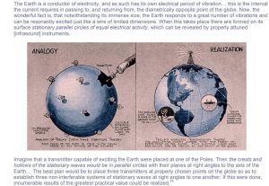
Canadian Patent No: 142,352, 1906-04-17, 1912-08-13 To all whom it may concern:  Be it known that I, Nikola Tesla, a citizen of the United States, residing in the Borough of Manhattan, in the City, County, and State of New York, have discovered a new and useful Improvement in the Art of Transmitting Electrical Energy Through the Natural Mediums of which the following is a specification, reference being had to the drawings accompanying and forming a part of the same. It is known since a long time that electric currents may be propagated through the earth, and this knowledge has been utilized in many ways in the transmission of signals and the operation of a variety of receiving devices remote from the source of energy, mainly with the object of dispensing with a return conducting-wire. It is also known that electrical disturbances may be transmitted through portions of the earth by grounding only one of the poles of the source, and this fact I have made use of in systems which I have devised for the purpose of transmitting through the natural media intelligible signals or power and which are now familiar; but all experiments and observations heretofore made have tended to confirm the opinion held by the majority of scientific men that the earth, owing to its immense extent, although possessing conducting properties, does not behave in the manner of a conductor of limited dimensions with respect to the disturbances produced, but, on the contrary, much like a vast reservoir or ocean, which, while it may be locally disturbed by a commotion of some kind remains unresponsive and quiescent in a large part or as a whole. Be it known that I, Nikola Tesla, a citizen of the United States, residing in the Borough of Manhattan, in the City, County, and State of New York, have discovered a new and useful Improvement in the Art of Transmitting Electrical Energy Through the Natural Mediums of which the following is a specification, reference being had to the drawings accompanying and forming a part of the same. It is known since a long time that electric currents may be propagated through the earth, and this knowledge has been utilized in many ways in the transmission of signals and the operation of a variety of receiving devices remote from the source of energy, mainly with the object of dispensing with a return conducting-wire. It is also known that electrical disturbances may be transmitted through portions of the earth by grounding only one of the poles of the source, and this fact I have made use of in systems which I have devised for the purpose of transmitting through the natural media intelligible signals or power and which are now familiar; but all experiments and observations heretofore made have tended to confirm the opinion held by the majority of scientific men that the earth, owing to its immense extent, although possessing conducting properties, does not behave in the manner of a conductor of limited dimensions with respect to the disturbances produced, but, on the contrary, much like a vast reservoir or ocean, which, while it may be locally disturbed by a commotion of some kind remains unresponsive and quiescent in a large part or as a whole.  Still another fact now of common knowledge is that when electrical waves or oscillations are impressed upon such a conducting-path as a metallic wire reflection takes place under certain conditions from the end of the wire, and in consequence of the interference of the impressed and reflected oscillations the phenomenon of “stationary waves” with maxima and minima in definite fixed positions is produced. In any case the existence of these waves indicates that some of the outgoing waves have reached the boundaries of the conducting-path and have been reflected from the same. Now I have discovered that notwithstanding its vast dimensions and contrary to all observations heretofore made the terrestrial globe may in a large part or as a whole behave toward disturbance impressed upon it in the same manner as a conductor of limited size, this fact being demonstrated by novel phenomena, which I shall hereinafter describe. Still another fact now of common knowledge is that when electrical waves or oscillations are impressed upon such a conducting-path as a metallic wire reflection takes place under certain conditions from the end of the wire, and in consequence of the interference of the impressed and reflected oscillations the phenomenon of “stationary waves” with maxima and minima in definite fixed positions is produced. In any case the existence of these waves indicates that some of the outgoing waves have reached the boundaries of the conducting-path and have been reflected from the same. Now I have discovered that notwithstanding its vast dimensions and contrary to all observations heretofore made the terrestrial globe may in a large part or as a whole behave toward disturbance impressed upon it in the same manner as a conductor of limited size, this fact being demonstrated by novel phenomena, which I shall hereinafter describe.  In the course of certain investigations which I carried on for the purpose of studying the effects of lightning discharges upon the electrical condition of the earth I observed that sensitive receiving instruments arranged so as to be capable of responding to electrical disturbances created by the discharges at times failed to respond when they should have done so, and upon inquiring into the causes of this unexpected behavior I discovered it to be due to the character of the electrical waves which were produced in the earth by the lightning discharges and which had nodal regions following at definite distances the shifting source of the disturbances. From data obtained in a large number of observations of the maxima and minima of these waves I found their length to vary approximately from twenty-five to seventy kilometer and these results and certain theoretical deductions led me to the conclusion that waves of this kind may be of still more widely differing lengths, the extreme limits being imposed by the physical dimensions and properties of the earth. In the course of certain investigations which I carried on for the purpose of studying the effects of lightning discharges upon the electrical condition of the earth I observed that sensitive receiving instruments arranged so as to be capable of responding to electrical disturbances created by the discharges at times failed to respond when they should have done so, and upon inquiring into the causes of this unexpected behavior I discovered it to be due to the character of the electrical waves which were produced in the earth by the lightning discharges and which had nodal regions following at definite distances the shifting source of the disturbances. From data obtained in a large number of observations of the maxima and minima of these waves I found their length to vary approximately from twenty-five to seventy kilometer and these results and certain theoretical deductions led me to the conclusion that waves of this kind may be of still more widely differing lengths, the extreme limits being imposed by the physical dimensions and properties of the earth. 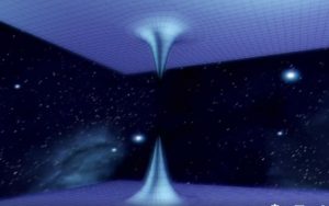 Recognising in the existence of these waves an unmistakable evidence that the disturbance created had been conducted from their origin to the most remote portions of the globe and had been thence reflected, I conceived the idea of producing such waves in the earth by artificial means with the object of utilising them for many useful purposes or which they are or might be found applicable. This problem was rendered extremely difficult owing to the immense dimensions of the planet, and consequently enormous of electricity or rate at which electrical energy had be delivered in order to approximate, even in a remote degree, movements or rates which are manifestly attained in the displays of electrical forces in nature and which seamed at first unrealisable by any human agencies; but by gradual and continuous improvements of a generator of electrical oscillations, which I have described in my United States patents Nos. 646,576 and 649,621, I finally succeeded in reaching electrical movements or rates of delivery of electrical energy not only approximating, but, as shown in many comparative tests and measurements, actually surprising those of lightning discharges, and by means of this apparatus I have found it possible to reproduce whenever desired phenomena in the earth the same as or similar to those due to such discharges. Recognising in the existence of these waves an unmistakable evidence that the disturbance created had been conducted from their origin to the most remote portions of the globe and had been thence reflected, I conceived the idea of producing such waves in the earth by artificial means with the object of utilising them for many useful purposes or which they are or might be found applicable. This problem was rendered extremely difficult owing to the immense dimensions of the planet, and consequently enormous of electricity or rate at which electrical energy had be delivered in order to approximate, even in a remote degree, movements or rates which are manifestly attained in the displays of electrical forces in nature and which seamed at first unrealisable by any human agencies; but by gradual and continuous improvements of a generator of electrical oscillations, which I have described in my United States patents Nos. 646,576 and 649,621, I finally succeeded in reaching electrical movements or rates of delivery of electrical energy not only approximating, but, as shown in many comparative tests and measurements, actually surprising those of lightning discharges, and by means of this apparatus I have found it possible to reproduce whenever desired phenomena in the earth the same as or similar to those due to such discharges. 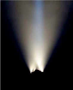 With the knowledge of the phenomena discovered by me and the means at command for accomplishing these results I am enabled not only to carry out many operations by the use of known instruments, but also to offer a solution for many important problems involving the operation or control of remote devices which for want of this knowledge and the absence of these means have heretofore been entirely impossible. For example, by the use of such a generator of stationary waves and receiving apparatus properly placed and adjusted in any other locality, however remote, it is practicable to transmit intelligible signals or to control or actuate at will any one or all of such apparatus for many other important and valuable purposes, as for indicating wherever desired the correct time of an observatory or for ascertaining the relative position of a body or distance of the same with reference to a given point or for determining the course of a moving object, such as a vessel at sea, the distance traversed by the same or its speed, or for producing many other effects at a distance dependent on the intensity, wave length, direction or velocity of movement, or other feature or property of disturbances of this character. I shall typically illustrate the manner of applying my discovery by describing one of the specific uses of the same -namely, the transmission of intelligible signals or messages between distant points – and with this object reference is now made to the accompanying drawings, in which – Figure 1 represents diagrammatically the generator which produces stationary waves in the earth, and Fig. 2 an apparatus situated in a remote locality for recording the effects of these waves. In Fig. 1, A designates a primary coil forming part of a transformer and consisting generally of a few turns of a stout cable of inappreciable resistance, the ends of which are connected to the terminals of a source of powerful electrical oscillations, diagrammatically represented by D. This source is usually a condenser charged to a high potential and discharged in rapid succession through the primary, as in a type of transformer invented by me and now well known; but when it is desired to produce stationary waves of great lengths an alternating dynamo of suitable construction may be used to energize the primary A. C is a spirally-round secondary coil within the primary having the end nearer to the latter connected to the ground E and the other end to an elevated terminal D. The physical constants of coil C, determining its period of vibration, are so chosen and adjusted that the secondary system C D is in the closest possible resonance with the oscillations impressed upon it by the primary A. It is, moreover, of the greatest importance in order to still further enhance the rise of pressure and to increase the electrical movement in the secondary system that its resistance be as small as practicable and its self-induction as large as possible under the conditions imposed. The ground should be made with great care, with the object of reducing its resistance. Instead of being directly grounded, as indicated, the coil C may be joined in series or otherwise to the primary A, in which case the latter will be connected to the plate E; but be it that none or a part or all of the primary or exciting turns are included in the coil C the total length of the conductor, from the ground-plate E to the elevated terminal D should be equal to one-quarter of the wave length of the electrical disturbance in the system E C D or else equal to that length multiplied by an odd number. This relation being observed, the terminal D will be made to coincide with the points of maximum pressure in the secondary or excited circuit, and the greatest flow of electricity will take place in the same. In order to magnify the electrical movement in the secondary as much as possible, it is essential that its inductive connection with the primary A should not be very intimate, as in ordinary transformers, but loose, so as to permit free oscillation – that is to say, their mutual induction should be small. The spiral form of coil C secures this advantage, wile the turns near the primary A are subjected to a strong inductive action and develop a high initial electromotive force. These adjustments and relations being carefully completed and other constructive features indicated rigorously observed, the electrical movement produced in the secondary system by the inductive action of the primary A will be enormously magnified, the increase being directly proportionate to the inductance and frequency and inversely to the resistance of the secondary system. I have found it practicable to produce in this manner an electrical movement thousands of times greater than the initial that is, the one impressed upon the secondary by the primary A and I have thus reached activities or rates of flow of electrical energy in the system E C D measured by many tens of thousands of horsepower. Such immense movements of electricity give rise to a variety of novel and striking phenomena, among which are those already described. The powerful electrical oscillations in the system E C D being communicated to the ground cause corresponding vibrations to be propagated to distant parts of the globe, whence they are reflected and by interference with the outgoing vibrations produce stationary waves the crests and hollows of which lie in parallel circles relatively to which the ground–plate E may be considered to be the pole. Stated otherwise, the terrestrial conductor is thrown into resonance with the oscillations impressed upon it just like a wire. More than this, a number of facts ascertained by me clearly show that this movement of electricity through it follows certain laws with nearly mathematical rigor. For the present it will be sufficient to state that the planet behaves like a perfectly smooth or polished conductor of inappreciable resistance with capacity and self-induction uniformly distributed along the axis of symmetry of wave propagation and transmitting slow electrical oscillations without sensible distortion and attenuation. Besides the above three requirements seem to be essential to the establishment of the resonating condition. With the knowledge of the phenomena discovered by me and the means at command for accomplishing these results I am enabled not only to carry out many operations by the use of known instruments, but also to offer a solution for many important problems involving the operation or control of remote devices which for want of this knowledge and the absence of these means have heretofore been entirely impossible. For example, by the use of such a generator of stationary waves and receiving apparatus properly placed and adjusted in any other locality, however remote, it is practicable to transmit intelligible signals or to control or actuate at will any one or all of such apparatus for many other important and valuable purposes, as for indicating wherever desired the correct time of an observatory or for ascertaining the relative position of a body or distance of the same with reference to a given point or for determining the course of a moving object, such as a vessel at sea, the distance traversed by the same or its speed, or for producing many other effects at a distance dependent on the intensity, wave length, direction or velocity of movement, or other feature or property of disturbances of this character. I shall typically illustrate the manner of applying my discovery by describing one of the specific uses of the same -namely, the transmission of intelligible signals or messages between distant points – and with this object reference is now made to the accompanying drawings, in which – Figure 1 represents diagrammatically the generator which produces stationary waves in the earth, and Fig. 2 an apparatus situated in a remote locality for recording the effects of these waves. In Fig. 1, A designates a primary coil forming part of a transformer and consisting generally of a few turns of a stout cable of inappreciable resistance, the ends of which are connected to the terminals of a source of powerful electrical oscillations, diagrammatically represented by D. This source is usually a condenser charged to a high potential and discharged in rapid succession through the primary, as in a type of transformer invented by me and now well known; but when it is desired to produce stationary waves of great lengths an alternating dynamo of suitable construction may be used to energize the primary A. C is a spirally-round secondary coil within the primary having the end nearer to the latter connected to the ground E and the other end to an elevated terminal D. The physical constants of coil C, determining its period of vibration, are so chosen and adjusted that the secondary system C D is in the closest possible resonance with the oscillations impressed upon it by the primary A. It is, moreover, of the greatest importance in order to still further enhance the rise of pressure and to increase the electrical movement in the secondary system that its resistance be as small as practicable and its self-induction as large as possible under the conditions imposed. The ground should be made with great care, with the object of reducing its resistance. Instead of being directly grounded, as indicated, the coil C may be joined in series or otherwise to the primary A, in which case the latter will be connected to the plate E; but be it that none or a part or all of the primary or exciting turns are included in the coil C the total length of the conductor, from the ground-plate E to the elevated terminal D should be equal to one-quarter of the wave length of the electrical disturbance in the system E C D or else equal to that length multiplied by an odd number. This relation being observed, the terminal D will be made to coincide with the points of maximum pressure in the secondary or excited circuit, and the greatest flow of electricity will take place in the same. In order to magnify the electrical movement in the secondary as much as possible, it is essential that its inductive connection with the primary A should not be very intimate, as in ordinary transformers, but loose, so as to permit free oscillation – that is to say, their mutual induction should be small. The spiral form of coil C secures this advantage, wile the turns near the primary A are subjected to a strong inductive action and develop a high initial electromotive force. These adjustments and relations being carefully completed and other constructive features indicated rigorously observed, the electrical movement produced in the secondary system by the inductive action of the primary A will be enormously magnified, the increase being directly proportionate to the inductance and frequency and inversely to the resistance of the secondary system. I have found it practicable to produce in this manner an electrical movement thousands of times greater than the initial that is, the one impressed upon the secondary by the primary A and I have thus reached activities or rates of flow of electrical energy in the system E C D measured by many tens of thousands of horsepower. Such immense movements of electricity give rise to a variety of novel and striking phenomena, among which are those already described. The powerful electrical oscillations in the system E C D being communicated to the ground cause corresponding vibrations to be propagated to distant parts of the globe, whence they are reflected and by interference with the outgoing vibrations produce stationary waves the crests and hollows of which lie in parallel circles relatively to which the ground–plate E may be considered to be the pole. Stated otherwise, the terrestrial conductor is thrown into resonance with the oscillations impressed upon it just like a wire. More than this, a number of facts ascertained by me clearly show that this movement of electricity through it follows certain laws with nearly mathematical rigor. For the present it will be sufficient to state that the planet behaves like a perfectly smooth or polished conductor of inappreciable resistance with capacity and self-induction uniformly distributed along the axis of symmetry of wave propagation and transmitting slow electrical oscillations without sensible distortion and attenuation. Besides the above three requirements seem to be essential to the establishment of the resonating condition.  First. The earth’s diameter passing through the pole should be an odd multiple of the quarter wavelength – that is, of the ratio between the velocity of light – and four times the frequency of the currents. Second. It is necessary to employ oscillations in which the rate of radiation of energy into space in the form of hertzian or electromagnetic waves is very small. To give an idea, I would say that the frequency should be smaller than twenty thousand per second, through shorter waves might be practicable. The lowest frequency would appear to be six per second, in which case there will be but one node, at or near the ground-plate, and, paradoxical as it may seem, the effect will increase with the distance and will be greatest in a region diametrically opposite the transmitter. With oscillations still slower the earth, strictly speaking, will not resonate, but simply act as a capacity, and the variation of potential will be more or less uniform over its entire surface. Third. The most essential requirement is, however, that irrespective of frequency the wave or wave-train should continue for a certain interval of time, which I have estimated to be not less than one-twelfth or probably 0.08484 of a second and which is taken in passing to and returning from the region diametrically opposite the pole over the earth’s surface with a mean velocity of about four hundred and seventy-one thousand two hundred and forty kilometers per second. [471,240 km/sec.] The presence of the stationary waves may be detected in many ways. For instance, a circuit may be connected directly or inductively to the ground and to an elevated terminal and tuned to respond more effectively to the oscillations. Another way is to connect a tuned circuit to the ground at two points lying more or less in a meridian passing through the pole E or, generally stated, to any two points of a different potential. First. The earth’s diameter passing through the pole should be an odd multiple of the quarter wavelength – that is, of the ratio between the velocity of light – and four times the frequency of the currents. Second. It is necessary to employ oscillations in which the rate of radiation of energy into space in the form of hertzian or electromagnetic waves is very small. To give an idea, I would say that the frequency should be smaller than twenty thousand per second, through shorter waves might be practicable. The lowest frequency would appear to be six per second, in which case there will be but one node, at or near the ground-plate, and, paradoxical as it may seem, the effect will increase with the distance and will be greatest in a region diametrically opposite the transmitter. With oscillations still slower the earth, strictly speaking, will not resonate, but simply act as a capacity, and the variation of potential will be more or less uniform over its entire surface. Third. The most essential requirement is, however, that irrespective of frequency the wave or wave-train should continue for a certain interval of time, which I have estimated to be not less than one-twelfth or probably 0.08484 of a second and which is taken in passing to and returning from the region diametrically opposite the pole over the earth’s surface with a mean velocity of about four hundred and seventy-one thousand two hundred and forty kilometers per second. [471,240 km/sec.] The presence of the stationary waves may be detected in many ways. For instance, a circuit may be connected directly or inductively to the ground and to an elevated terminal and tuned to respond more effectively to the oscillations. Another way is to connect a tuned circuit to the ground at two points lying more or less in a meridian passing through the pole E or, generally stated, to any two points of a different potential. |

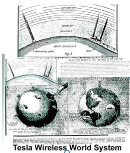
Tesla’s ‘world system’ was conceptually based on three of his inventions:
- The Tesla Transformer (Tesla coil)
- The Magnifying Transmitter (transformer adapted to excite the Earth)
- The Wireless System (efficient transmission of electrical energy without wires)
Tesla stated:
“The first World System power plant can be in operation in nine months. With this power plant it will be practicable to attain electrical activities of up to ten million horsepower (7.5 billion watts), and it is designed to serve for as many technical achievements as are possible without due expense.”
Tesla’s calculated power levels have been conservatively estimated and recently updated with contemporary physics calculations by Dr Elizabeth Rauscher. For example, Professor Rauscher shows that the Earth’s ionosphere and magnetosphere contain sufficient potential energy, at least three billion kilowatts (three terawatts) respectively, so that the resonant excitation of the Earth-ionosphere cavity can reasonably be expected to increase the amplitude of natural ‘Schumann’ frequencies, facilitating the capture of useful electrical power. Tesla knew that the earth could be treated as one big spherical conductor and the ionosphere as another, bigger, spherical conductor, so that together they have parallel plates and thus comprise a “spherical capacitor”. Rauscher calculates the capacitance to be about 15,000 microfarads for the complete Earth-ionosphere cavity capacitor. What I claim as my invention is: 1. The art herein described for transmitting electrical energy to a distance consisting in establishing stationary electrical waves in the earth by impressing thereon electrical oscillations of definite frequency. 2. The art herein described for transmitting electrical energy to a distance consisting in establishing electrical oscillations and impressing said oscillations upon the earth and producing therein stationary electric waves. 3. The art herein described for transmitting and utilising electrical energy consisting in establishing stationary electrical waves in the earth, and operating thereby one or more receiving devices remote from the source of energy. 4. The art herein described for transmitting and utilising electrical energy consisting in establishing stationary electrical waves in the earth, and operating thereby one or more receiving devices remote from the source of energy and proprly located with respect to the position of said waves. 5. The art herein described for transmitting and utilising electrical energy consisting in establishing stationary electrical waves in the earth, and varying the length of such waves. 6. The art herein described for transmitting and utilising electrical energy consisting in establishing stationary electrical waves in the earth, and shifting the nodal and ventral region of said waves. 7. The art herein described for transmitting electrical energy consisting in producing stationary electrical oscillations of definite length, impressing said oscillations upon the natural conducting medium and causing thereby a resultant wave or affect to travel slowly over said medium. 8. The art herein described for transmitting electrical energy which consists in establishing stationary electrical waves of different length varying the length of said waves and causing thereby a resultant wave or affect to travel with the desired velocity throughout the natural medium. 9. The art herein described for transmitting and utilising electrical energy consisting in establishing stationary electrical waves, impressing said waves upon the natural conducting medium, varying the intensity of said waves and producing thereby perceptible effects in distant receivers. 10. The art of producing affects at a distance consisting in establishing stationary electrical waves, impressing said waves upon the terrestrial globe, varying the characteristics and relations of said waves and causing thereby affects in distant receivers. 11. The art herein described for transmitting and utilizing electrical energy consisting in establishing stationary electrical waves, impressing the affect of said waves upon the natural medium, positioning receiving apparatus at different places through said medium and determining from the affects or indications of said receiving apparatus the condition of said medium. 12. The art herein described for transmitting electrical energy consisting in establishing electrical waves of definite length and duration and impressing said waves upon the natural medium and thereby throwing said natural medium into resonance. 13. The art herein described for creating great electrical movements in the natural medium, which consists in establishing electrical waves of definite length and duration and impressing said waves upon said natural medium until the same becomes resonant. 14. In a system for the transmission of electrical energy, transmitting apparatus comprising a primary exciting circuit energized by a generator of alternating currents and a resonant secondary circuit of high self-induction and small resistance loosely linked with the primary and adapted for throwing the terrestrial globe into resonance, as set forth. 15. In the system for the transmission of electrical energy, a source of primary electrical oscillations such as a condenser circuit and a secondary circuit inductively linked with the same and adapted for throwing the terrestrial globe into resonance, as specified.
WIRELESS TRANSMISSION THEORY |
 |
|
|
“By the plan I had conceived, if it was realizable, it was just as easy to telegraph or telephone across the entire globe as it is across this room.” – Nikola Tesla, 1916 |
||
|
In the late 19th century, shortly after the introduction of AC power, Nikola Tesla began development of a system for the global transmission of electrical energy without interconnecting wires. Some of his early apparatus took the form of ordinary radio transmitters, much like those used when commercial broadcasting and wireless telecommunications began to take hold in the 1920s. Others were resonant electrical induction apparatus used in a laboratory setting for electric lighting. The wireless “electrodynamic inductive” technique lay dormant for some 100 years until 2006, when it was revived before the public’s eyes under the name “Witricity” [1]. Unlike the two methods referred to above, the wireless method that Tesla planned to use at Wardenclyffe depends upon an electrical current flowing through the earth between a Tesla coil transmitter and a Tesla coil receiver. Both of the prototype transmitter-receiver stations would be built following the same design, with a powerful Tesla coil located inside each of the tower structures. In the case of Wardenclyffe prototype, the second plant was to be constructed somewhere in Great Britain, perhaps on the west coast of Scotland near Glasgow or to the south in Cornwall. The atmospheric conduction method depends upon the passage of electrical current through both the earth and the atmosphere.
The electric current through the earth is balanced by an equivalent electrical displacement through the space above it. This displacement can be achieved by means of electrical conduction through the atmosphere without violating any of the known laws of physics. With energy transmission by true electrical conduction, a very high voltage on the order of 15 million volts is needed on both of the elevated terminals to break down the insulating air around and above each plant. The ionization of the atmosphere directly above the elevated terminals is facilitated by a vertical ionizing beam of ultraviolet radiation that leads to the formation of what might be called a plasma high-voltage electrical transmission line. The upper troposphere between the transmitter and the receiver is available for a conductor by inducing the plasma state within that region. This is the “aurora” effect described by Tesla in the 1916 interview.
The end result is a flow of true conduction currents between the two elevated terminals by a path up to and through the troposphere, and back down to the other facility. To learn more about this mode of operation read the paper “Nikola Tesla On Wireless Energy Transmission, with additional comments by Henry Bradford and Gary Peterson” located at, http://www.teslaradio.com/pages/tesla.htm.In addition to the atmospheric-conduction method the Tesla coil transmitter design is also adaptable to another method that Tesla had for wireless transmission called “earth resonance.” Comparing Tesla’s patents covering his wireless system using the earth resonance method and those covering the atmospheric conduction method reveals that both the basic transmitting and receiving apparatus are identical. Both consist of large Tesla coils connected to the earth and to high-voltage elevated terminals. (It is important to note that a single earth-resonance Tesla coil transmitter can be made to perform exactly as intended without any additional stations being present. In this case the earth itself overrides the requirement that one or more additional stations be placed into operation.) Differences between the two methods are the potential required at the Tesla coil transmitter’s elevated terminal and also the operating frequency. For atmospheric conduction about 15 to 20 million volts are needed. For earth resonance Tesla says the elevated terminal has to be charged up to about 100 million volts. As for frequency, the usable base frequency spectrum is about the same for both methods, about 1,000 to 35,000 cycles per second (1-35 kHz). An atmospheric conduction system can operate at any arbitrarily selected frequency in this region. With an earth resonance system it is compulsory that it operate on some harmonic of the fundamental earth-resonance frequency, reported by Tesla as being about 12 Hz. There is a misconception among some researchers that Tesla intended to transmit electrical energy directly through the Schumann cavity or earth-ionosphere cavity. While he definitely spoke of exciting a terrestrial resonance mode, he was not talking about the direct excitation of a Schumann resonance. The terrestrial resonance mode that he apparently excited in 1899 at Colorado Springs is referred to by some as an “earth resonance mode,” which are different from the Schumann resonance modes. Also remember that Tesla made a distinction between electrical energy transmission by atmospheric conduction and electrical energy transmission using earth resonance principles.
One final note, the earth possesses a naturally existing negative charge with respect to the conducting region of the atmosphere beginning at an elevation of about 50 kilometers. The potential difference between the earth and this region is on the order of 400,000 volts. Near the earth’s surface there is a ubiquitous downward directed E-field of about 100 V/m. In LIGHTNING PROTECTOR, May 6, 1916, U.S. Patent 1,266,175, May 14, 1918 Tesla referred to this charge as the “electric niveau” or electric level.
Tesla coil earth resonance transmitters create a local disturbance in the earth’s charge that appear as an annular deviation in the strength of the background electric field. In operation, successive disturbances move away from the transmitter and diminish in intensity as the distance from the transmitter increases. A sufficiently powerful transmitter produces electric field distortions that propagate all the way to the antipode at which point the energy is reflected back towards its point of origin. When properly tuned, constructive interference occurs between the outgoing disturbances and the reflected disturbances returning from the antipode. The transmission of electrical energy across the entire globe and its reflection all the way back to its source is the basis of Tesla’s earth resonance method. While the atmospheric conduction method requires that both transmitting and receiving apparatus be placed into operation, a properly tuned and sufficiently powerful earth resonance transmitter, on the other hand, can be made to operate exactly as intended without any man-made Tesla coil receivers being activated. The earth itself fulfills the requirement that a synchronized receiver be present. To conclude this section, three fundamental principles behind the operation of Tesla’s global wireless telecommunications system are: 1. Low frequency alternating current can be transmitted through the inhomogeneous earth with low loss due to the fact that the net resistance between antipodes of the earth is considerably less than 1 ohm. The electrical displacement takes place predominantly by electrical conduction through the more conductive regions. The electrical energy also propagates through the earth by means of electrostatic induction or displacement current. 2. Low frequency high voltage alternating current can be transmitted through the atmosphere with low loss. The electrical displacement takes place by a) electrostatic induction, b) electrical conduction, or a combination of these two. 3. The earth possesses a naturally existing negative charge or DC electrostatic potential, on the order of 400,000 volts, with respect to the conducting region of the atmosphere beginning at an elevation of about 50 kilometers, and near the earth’s surface there is a ubiquitous downward directed E-field of about 100 V/m. The Tesla coil transmitter creates a disturbance in this charge, which may be observed as an annular distortion of the background electric field around it. Wireless Energy Transmission for the Amateur Tesla Coil Builder (Re: [TCML] Wireless Transmission Theory)“Since charge is conserved, scalar field S satisfies the homogeneous wave equation, thus one should expect primarily sources of dynamic scalar fields, and not sources of static scalar fields.” – Koen J. van Vlaenderen, 2008 One disagreement yet to be resolved about the Tesla wireless system is whether electrical energy is carried from Tesla coil transmitters to Tesla coil receivers by ordinary radio waves or if some other mechanism is involved. We are speaking here of scaled-down versions of the system such as might be assembled by the typical Tesla coil experimenter. The operational power levels involved are assumed to be insufficient to excite earth resonance or result in massive atmospheric ionization in the vicinity of the oscillators. There are no provisions for the generation of vertical ionizing beams originating at the elevated terminals and projecting up to an elevation of say 8 km where conductivity can more easily be imparted to the air. Nine Proposed Mechanisms Regarding the transmission of electrical energy from a Tesla coil transmitter to a Tesla coil receiver, six possible mechanisms have been identified that are available according to present electromagnetic field theory. The first three are mutual induction, capacitance, and far-field electromagnetic radiation or ordinary radio waves. The fourth is an alternative mechanism involving ordinary radio waves produced in the far-field zone as a result of ground currents propagating to a great distance from operating Tesla coil transmitters. The fifth model is that of energy transmission by means of a spherical conductor “single-wire” surface wave transmission line. (There may be aspects of the physics behind the single wire transmission line that are not fully understood.)[2] The sixth mechanism is modulation of the natural plasma that exists because of the electrical potential gradient between the earth’s surface and the conducting region of the atmosphere beginning at about 50 kilometers. The seventh mechanism is what might be called “electrostatic induction.” This explanation exists within a ‘grey area’ of electromagnetic field theory. The eighth proposed mechanism is propagation by means of an ion-acoustic wave in the intervening space between the two elevated terminals. This is a special case where the operational power levels involved are sufficient to result in massive atmospheric ionization in the vicinity of the two transmission – reception stations, and provisions are made for the generation of vertical ionizing beams originating at the elevated terminals and projecting up to an elevation of say 8 km where conductivity can more easily be imparted to the air. [3] The ninth proposed mechanism considers the transmitter and receiver as being “self-referencing” by means of virtual electrical grounds, a theoretical concept developed by Eric Dollard and others in the 1980s. This is another special case, that in which the operational power levels involved are sufficient to excite earth resonance. [4] Mutual induction Energy transmission by “mutual induction” can be excluded because the magnetic field density falls off too rapidly to account for amount of energy received in the far-field zone. Furthermore, the transfer of energy between a Tesla coil transmitter and the requisite Tesla coil receiving transformer involves electrical conduction between the two respective ground terminals, and this is not taken into account by this model Capacitive coupling (differential capacitance) The elevated terminal of a Tesla coil transmitter works as a capacitor plate. Opposite to this plate is every other electrically conducting body to which it is connected, including the earth and the receiving transformer’s elevated terminal. The transmitter’s elevated terminal serves two purposes: first, it acts as a charge reservoir in relation to the earth’s surface in the immediate vicinity of the transmitter; second, it is one of two electrodes, the other electrode being the receiving facility’s elevated terminal. Ed Phillips has observed, “the coupling inferred by Tesla’s use of this figure [below] and the notation of charge which goes with it would be that of mutual capacitance.”
For distances up to about 1/6-1/2 wavelength the propagation of energy between the respective elevated terminals is a result of displacement current, exactly like the transfer of electrical energy between two closely-spaced plates of a conventional capacitor in a typical AC circuit. This explanation is fine for distances up to about 1/2 wavelength, but the electric field intensity between two capacitor plates, mathematically modeled using a low-voltage DC potential, is a near-field phenomenon. In other words, at greater distances the standard mathematical capacitive coupling model breaks down. A.C. de Queiroz, says this:
Therefore, energy transmission by capacitive coupling would seem to be excluded because when the two elevated terminals are separated by more than about one-half of a wavelength of the applied current they are, in theory, electrically decoupled.
Far-field electromagnetic radiation or ordinary radio waves Any well-designed Tesla coil transmitter can be shown to be a poor source of radio waves, in both the near field and the far field. Field strength measurements taken on actual Tesla coil transmitters demonstrate that when these devices are in a higher state of refinement they are very inefficient in terms of the production of electromagnetic radiation, a.k.a. “radio waves.” There is insufficient signal strength to account for the amount of energy received in the far-field zone. In light of this, ordinary radio waves can be excluded. The Bradford Hypothesis The basic idea is that the earth currents and charge-coupled electromagnetic field associated with Tesla coil transmissions gradually decouple from the associated charge carriers and become ordinary radio waves as a function of the distance from the transmitter. Mr. Bradford states, “I do not believe that the theory for it has been worked out, but in principle it is a straightforward application of electromagnetic theory.” 1) The Spherical Conductor “Single-wire” Surface Wave Transmission Line model This explanation, presently being refined by Kenneth and James Corum, et al, is a strong candidate. A Tesla coil transmitter consisting of a grounded high voltage, pulse-driven, top-loaded helical resonator launches a transmission-line wave or surface wave, in the form of earth currents and a charge-coupled electromagnetic field. It is somewhat similar to the G-line or Goubau transmission line model promoted by William Beaty. There is even better agreement with the E-line transmission line model described by Glenn Elmore. This model is based upon a sometimes overlooked solution to the Maxwell-Heaviside equations that describes a propagating TM00 surface wave on a single conductor. This “nonradiating surface wave mode . . . exhibits attenuation much lower than coax and a relative propagation velocity of unity. . . . It is very broadband and has practical applications from RF through microwave frequencies and beyond. . . .” (see Elmore, Glenn, “Introduction to the Propagating Wave on a Single Conductor,” 2009 ; http://www.corridor.biz/FullArticle.pdf ). The terrestrial surface wave or surface plasmon associated with Tesla wireless system apparatus is the result of current flowing between two discrete points of direct electrical connection to the earth’s subsurface, one at the transmitter and the other at the receiver. 2) Modulation of naturally existing plasma model The entire earth possesses a naturally existing negative charge or DC electrostatic potential with respect to the conducting region of the atmosphere beginning at an elevation of about 50 kilometers. The potential difference between the earth and this region is on the order of 400,000 volts. Near the earth’s surface there is a ubiquitous downward directed E-field of about 100 V/m. In operation, a grounded Tesla coil transmitter creates a local disturbance in this charge. The disturbance manifests itself as an annular distortion of the background electric field around the transmitters ground terminal. At a point in time when a measurement of the e-field component of the EM field at the ground terminal should show zero volts above the background potential, other measurements should show it rising in intensity until a point 1/4 wavelength (1/4 lambda) away from the ground terminal is reached (axial projection). From there the e-field should diminish in intensity until, at 1/2 wavelength from the terminal, it again shows zero. At a measurement point approximately one wavelength away from the ground terminal, an induced e-field once again should begin to emerge above the average background field level, again increasing in intensity until a second maxim is reached at 1 1/4 wavelengths away from the oscillator. It is possible that measurements would reveal a zero crossing to a relative potential of the opposite sign. With a sufficiently powerful transmitter this phenomenon would be expected to repeat itself over and over until the antipode is reached, at which point reflection would take place and the transmitted energy would begin to travel back to its point of origin in the reverse direction. With the proper selection of operating frequency constructive interference with the outgoing wave takes place. 3) “Electrostatic induction” In this model the two distant elevated terminals are electrically coupled together in a manner similar to the transfer of electrical energy between two closely spaced capacitor plates in a typical AC circuit, but at distances greatly exceeding 1/6 – 1/2 wavelength. The electric field between the two elevated terminals is not homogeneous but has persistent wave properties. (These persistent structures in the E-field have been called “potential vortices” by Konstantine Meyl, see “Scaling Down Tesla’s Wireless System for Experimentation.” Tesla used the term electrostatic induction to describe the behavior of capacitors, or more generally, the electrical coupling of two or more conducting surfaces that are separated by one form or another of dielectric. This term appears in Tesla’s SYSTEM OF TRANSMISSION OF ELECTRICAL ENERGY (U.S. Patent No. 645,576, dated March 20, 1900) and elsewhere.
This model is inconsistent with a basic tenet of mainstream physics related to the scalar derivatives of the electromagnetic potentials, which as of the year 2013 are considered by many to be nonphysical. Notes: In all cases, with the exceptions of the mutual induction model, it is an absolute requirement that both the Tesla coil transmitter and the terrestrial Tesla coil receiver be well connected to the earth’s subsurface, allowing them to be coupled together by electrical conduction through the earth between their ground terminals. Also, the transmitter excitation current will typically be ‘mono-polar’ transient in nature, that is to say non-sinusoidal with a rapid rise time and cutoff. It is quite conceivable that it will be found the best explanation for the long-distance transmission of electrical energy between a Tesla transmitter and receiver is a combination of two or more of the three best-candidate mechanisms listed above. Yahoo Wireless Energy Transmission Tech Group Message #787 Re: The nine proposed mechanisms > 9) “Electrostatic induction” > For distances beyond about 1/2 wavelength the propagation of energy > between the respective elevated terminals is the result of what might > be called electrostatic induction” somewhat like the transfer of . . . Instead of “electrostatic induction,” this should probably be called “waves of dielectric polarization” Analogy: a long cylindrical coil behaves as a VLF waveguide. So does a long iron rod: we can wrap a “transmitter” coil at on end of a long iron core, and wrap a “receiver” coil around the far end. If instead of iron we use a long plastic rod, and we place a capacitor plate at each end, we form a low-frequency waveguide. But rather than relying on progressive propagation of magnetic fields as with the long coil or the long iron core, the plastic rod relies on progressive propagation of e-fields. Because the dielectric constant of the rod is higher than that of the surrounding air, the e-fields will be guided by the rod. Or said another way: the “transmitting” plate causes the adjacent part of the plastic rod to become electrically polarized, which polarizes the next part, which polarizes the next. The plastic behaves as a conductor for displacement current. Perhaps it helps to imagine using a Barium Titanate or PZT ceramic rod, which “guides” e-fields better than the air by a factor of many thousands. If such dielectric waves are actually emitted by the ground terminal of a Tesla coil transmitter secondary, they might spread as sphere-waves through the bulk the planet (though probably blocked and reflected by the Earth’s iron core.) They probably have a very different velocity than any kinds of EM waves traveling around the Earth via surface waves or via the atmospheric ducting effect. And so they’d show Earth-resonant frequencies different than those detected by antennas in the air. (Perhaps use deeply buried loop or dipole antennas to detect the dielectric waves.) William BeatyYahoo Wireless Energy Transmission Tech Group Message #788 Thank you for your most valuable input. > . . . “waves of dielectric polarization.” I like “electrostatic induction” because that is the term Tesla uses. > If such dielectric waves are actually emitted by the ground terminal of a TC secondary . . . I envision the ground-terminal output as being electric current flowing into the conducting earth. For me the electrostatic induction [or propagation by “waves of dielectric polarisation” or “longitudinal waves” or “scalar waves”] is associated with the e-field that shows up at the elevated terminal, and the displacement current. Nevertheless, I’m willing to accept that the transmitted wave energy passes [through] the dielectric earth in addition to passing through the space just above it. >. . . Perhaps use deeply buried loop or dipole antennas to detect the dielectric waves . . . I think detection or reception of the electrostatic dielectric induction energy wave would best be done the exact same way that Tesla says to do it in the ‘earth resonance patent’ ART OF TRANSMITTING ELECTRICAL ENERGY THROUGH THE NATURAL MEDIUMS (U.S. Patent No. 787,412, April 18, 1905) the Canadian version of which located at, http://www.teslaradio.com/pages/patents/142352.htm , using a Tesla coil receiver or that other Tesla wireless system receiver set in between (see fig. 2 below). Gary Peterson June 16, 2008
In June 2008 Bill Beaty suggested the electrostatic induction that takes place between the ground terminal of a Tesla coil transmitter and the ground terminal of a paired up Tesla coil receiver in the form of “dielectric waves” or “waves of dielectric polarization” might be detected using a deeply buried dipole antenna. Rather than a dipole antenna it would be better to adopt the technique described by Tesla in the Canadian patent ART OF TRANSMITTING ELECTRICAL ENERGY THROUGH THE NATURAL MEDIUMS (U.S. Patent No. 787,412, April 18, 1905) located at, http://www.teslaradio.com/pages/patents/142352.htm .
An oscilloscope along with a bandpass filter or a spectrum analyzer, and an optional preamplifier [or attenuator] is used in the place of Tesla’s rotating cylindrical switcher-plus-sensitive-device to detect the transmitted electrical energy, i.e., the electrical energy being transmitted through the earth. The same instrumentation can also be used in conjunction with the Tesla coil receiving transformer. Coupling to the helical resonator is by means of either an E-field or an H-field probe.
[1] Soljacic, Marin, et al, “Wireless Power Transfer via Strongly Coupled Magnetic Resonances” SCIENCE, vol. 317, July 6, 2007 [2] Electromagnetic space wave radio propagation involves both sky-wave and ground-wave components. In turn, the ground wave has both direct-wave and ground-reflected components. The ground-reflected component reaches the radio wave receiving antenna after being reflected from the earth’s surface. There is also an induced ground-hugging component called the Norton surface wave. It is the result of electrical currents induced in the earth by refraction of a portion of the reflected-wave component at the earth-atmosphere interface. Upon reflection from the earth’s surface the reflected wave undergoes a 180deg phase reversal. When the transmitting antenna is on or close to the ground, the direct and reflected components tend to cancel out and the resulting field intensity is principally that of this surface wave. Because part of its energy is absorbed by the ground, the rate of attenuation is much greater than inversely as the distance. It is the conductivity of the underlying terrain that determines the attenuation of the Norton surface-wave field intensity as a function of distance. The ground currents of a vertically polarized Norton surface wave do not short-circuit a given electric field but rather serve to restore part of the used energy to the following field. The better the conducting surface layer, the more energy returned and the less energy absorbed. [Antennas and Radio Propagation, TM 11-666, Dept. of the Army, Feb. 1953, pp. 17-23.] Sommerfeld describes an electrodynamic wave that is guided along a wire of finite conductivity and Zenneck expands upon this description, asserting that the earth’s surface behaves in a manner similar to a conducting wire. While the Norton Surface Wave is the result of electrical currents induced in the earth by refraction of a portion of the reflected-wave component of the ground-wave at the earth-atmosphere interface, the Zenneck surface wave associated with Tesla’s apparatus is the result of terrestrial current flowing between discrete points of direct electrical connection to the earth’s subsurface. When compared with the Norton surface wave it appears the Zenneck surface wave does not diminish as significantly as the distance from the source facility increases.
[3] The electrostatic or magneto-hydrodynamic plasma wave model. In operation a radio-frequency current is applied to each of the two resonators creating, at each location, an oscillating magnetic field. In turn, the oscillating magnetic field induces an oscillating electric field. The oscillating electromagnetic field creates a weak to highly ionized plasma in the vicinity of each resonator, depending on the amount of power applied to the oscillation transformer primary. The volume of the ionized region is proportional to the peak energy of the oscillation. If the currents in the two resonators have a 180deg phase relationship with each other, then conditions are favorable for interconnection of their respective magnetic fields. In addition to the inductively coupled discharge created plasma, conditions also exist for the creation of capacitively coupled discharge plasma between the two respective elevated terminals. These would be either electrostatic waves or more likely magneto-hydrodynamic waves, assuming the presence of inter-connected magnetic field lines. The transfer of energy between a Tesla coil transmitter and the requisite Tesla coil receiving transformer is by electrical conduction through the earth between the two respective ground terminals, and also through artificially created weakly ionized plasma between the two elevated terminals. For a high-power system, coupling between the elevated terminals is by electrical conduction through highly ionized plasma. The two electrodes act as high voltage discharge terminals for the formation of capacitively coupled discharge plasma with the electrical interconnection taking place through the upper level atmosphere. The ionization of the denser atmosphere directly above the elevated terminals is facilitated by the use of an ionizing beam of high-intensity ultraviolet light to form what might be called a high-voltage plasma transmission line (see Barnes, Jr., Arnold A., Robert O. Berthel, “A Survey of Laser Lightning Rod Techniques,” AD-A239 988, August 21, 1991). [4] Virtual ground model. The transmitter and receiver are viewed as being “self-referencing” through the establishment of virtual electrical grounds comprised by the two elevated terminals. The system would use earth resonance to circumvent the Newtonian law of action and reaction.
Alternatively described, circumvention of Newton’s Third Law would be due to electrodynamic force interactions between heavy ions and electrons, known as the anomalous cathode reaction force.
[5] Fig. 14. Diagram Explaining the Relation Between the Effective and the Measured Current In the Antenna.
|


